WhatsApp:
+86 13188899036
Email:
[email protected]
Avoid your inquiry is delay response, please enter your WhatsApp/WeChat/Skype along with the message, so we can contact you at the very first time
We will reply you within 24 hours. If for urgent case, please add WhatsApp: +86 13188899036, or WeChat: 0531-87968777. Or call 0531-87968777 directly.
* We respect your confidentiality and all information are protected. We will only use your information to respond to your inquiry and will never send unsolicited emails or promotional messages.
Tired of inconsistent process results due to fluctuating flow, temperature, or pressure? Manual adjustments are often imprecise and slow, leading to inefficiency and potential quality issues. You need an automated solution for precise, stable control.
An electric regulating valve, also known as an electric control valve, is specifically designed for modulating service. Unlike simple on/off valves, it uses an electric actuator (driven by an electric motor) to precisely adjust the valve position anywhere between fully open and fully closed. This allows for fine-tuned control over flow rates, pressure, or temperature within a system, based on an incoming electric control signal (like 4-20mA or 0-10V). It’s the key to stable and efficient automated process control.
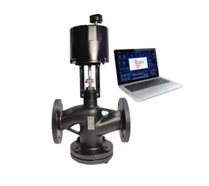
RS485 regulating valve
As a smart valve manufacturing plant, we see firsthand the critical need for precision in modern industries. Whether you’re a Building Automation Engineer optimizing HVAC efficiency, an Industrial Plant Manager ensuring process stability, or a Mechanical Contractor installing reliable systems, the ability to accurately regulate flow is paramount. The electric regulating valve represents a significant leap forward in achieving this level of control, offering reliability, integration ease, and the precision required for today’s demanding applications. Let’s delve into how these sophisticated devices work and why they are becoming indispensable.
At its heart, an electric regulating valve is a type of control valve designed not just to stop or start flow, but to modulate it. Think of it like a dimmer switch for fluids, rather than a simple on/off switch. It achieves this by pairing a valve body (which could be a globe valve, ball valve, butterfly valve, etc., chosen for the specific application) with a specialized electric actuator. This actuator contains an electric motor, gearing, and sophisticated control circuitry.
The key difference lies in how it’s instructed to operate. Instead of just receiving a signal to go fully open or fully closed, the regulating actuator accepts a variable analog control signal, typically industry standard formats like 4-20mA or 0-10V DC. This signal usually comes from a process controller, PLC (Programmable Logic Controller), or a building automation system. The actuator‘s internal electronics interpret this signal as a desired valve position (e.g., 4mA = closed, 12mA = 50% open, 20mA = fully open).
The actuator then drives the motor and gears to move the valve‘s flow-controlling element (like the plug in a globe valve or the ball in an electric regulating ball valve) to that precise position. Crucially, it often includes internal position feedback mechanisms (like a potentiometer or position transmitter) that constantly monitor the actual valve position. This feedback allows the actuator to compare the actual position with the desired position indicated by the control signal, making fine adjustments to ensure accuracy and hold the position steady, even against varying process forces like fluid pressure. This closed-loop operation within the actuator ensures precise and reliable modulation.
A complete electric regulating valve unit comprises several essential parts working together seamlessly. As manufacturers, we focus on the quality and integration of each element:
Valve Body: This is the pressure-containing housing connected to the pipeline. The internal design dictates how flow is controlled (e.g., globe, ball, butterfly). Material selection (e.g., cast iron, stainless steel, brass) is critical based on fluid compatibility, pressure, and temperature. The body’s shape and internal trim (plug, seat, cage, ball) directly influence the valve‘s flow characteristics (e.g., linear, equal percentage).
Internal Trim: These are the parts within the valve body that directly modulate the flow.
Globe Valve: Consists of a movable plug and a stationary seat ring. The shape of the plug determines the flow characteristic.
Ball Valve: Uses a rotary ball with a specifically shaped port (often V-shaped for regulation). An electric regulating ball valve offers good rangeability and tight shutoff.
Butterfly Valve: Uses a rotating disc. Often used for larger pipe sizes, but precise low-flow control can be challenging.
Electric Actuator: The ‘brain’ of the regulating valve. It houses:
Electric Motor: Provides the power to move the valve stem/shaft. Can be AC or DC.
Gearbox: Reduces motor speed and increases torque to operate the valve against process forces.
Control Circuitry: Receives and interprets the analog control signal (e.g., 4-20mA, 0-10V.DC or 1-5V.DC from computer), compares it to the feedback signal, and drives the motor. May include features like auto-calibration, diagnostic capabilities, and communication interfaces (e.g., HART, Modbus). Our RS485 regulating valve incorporates such communication capabilities.
Position Feedback Mechanism: Typically a potentiometer or a non-contact sensor that measures the exact rotational or linear position of the valve stem/shaft. This feedback is crucial for accurate positioning. It often instrument as well as outputs this position as a separate signal (e.g., 4-20mA) for system verification.
(Optional) Manual Override: A handwheel or lever to operate the valve manually if power is lost or during commissioning.
Mounting Hardware/Linkage: Securely connects the actuator to the valve body, ensuring proper alignment and force transmission. Industry standards like ISO 5211 often simplify direct mounting for rotary valves.
Understanding these components helps appreciate the engineering involved in creating a reliable and precise electric regulating valve assembly. The synergy between the mechanical valve design and the intelligent electric actuator is key to performance.
The fundamental difference lies in functionality and purpose. On/off valves (like manual valves or standard solenoid/actuated valves) have only two states: fully open or fully closed. They are designed for isolation or simple start/stop operations. Think of them as light switches – either completely on or completely off.
Electric regulating valves, on the other hand, are designed for modulation. They can achieve any position between fully open and fully closed, allowing for precise adjustment of the flow rate, pressure, or temperature. This is like a dimmer switch for lights, enabling you to set the brightness to any level you desire. This capability is achieved through the sophisticated electric actuator that responds to variable analog control signals (e.g., 4-20mA, 0-10V DC) rather than simple on/off voltage signals.
Here’s a table summarizing the key differences:
| Feature | On/Off Valve | Electric Regulating Valve |
| Primary Use | Isolation, Start/Stop Flow | Modulation, Precise Control |
| Positions | Fully Open, Fully Closed | Any position between 0% and 100% |
| Control Signal | Simple On/Off Voltage | Analog (e.g., 4-20mA, 0-10V) |
| Actuator Type | Basic Electric or Pneumatic | Modulating Electric Actuator |
| Feedback | Optional (Limit Switches) | Essential (Position Sensor/Transmitter) |
| Complexity | Simpler | More Complex Electronics |
| Application | Tank Fill, Line Isolation | Temp Control, Pressure Control, Flow Balancing |
While on/off valves are essential for many functions, electric regulating valves provide the fine-tuning capability required for stable and efficient process control and sophisticated building automation strategies. Our Switch regulating valve is an example of a simpler on/off type, whereas the Proportional regulating valve embodies the modulating principle.
Choosing an electric regulating valve for modulating control applications offers numerous benefits compared to other methods (like manual adjustment or sometimes pneumatic control):
Precision and Stability: The ability to precisely position the valve based on real-time process feedback leads to much more stable and accurate control of flow, temperature, or pressure. This results in consistent product quality, optimized processes, and improved comfort in HVAC systems.
Energy Efficiency: By precisely matching flow to demand, electric regulating valves help optimize energy consumption. In HVAC systems, this means avoiding over-cooling or over-heating. In industrial processes, it ensures pumps and heaters operate at optimal loads, reducing wasted energy. The electric actuator itself typically consumes power only when moving or holding against significant force, making it efficient.
Automation and Integration: These valves are designed for seamless integration into automated control systems (PLCs, DCS, BAS). They readily accept standard electric control signals and often provide feedback signals for monitoring and diagnostics, enabling centralized control and data logging.
Simplified Infrastructure: Unlike pneumatic regulating valves which require a complex infrastructure of compressed air lines, filters, regulators, and positioners, electric regulating valves only need electrical wiring for power and control signals. This simplifies installation, reduces potential leak points, and lowers maintenance overhead, especially where compressed air isn’t readily available.
Remote Operation and Adjustment: Setpoints and control parameters can be adjusted remotely through the control system, eliminating the need for manual intervention at the valve location, which might be hazardous or inaccessible.
Reliability and Reduced Maintenance: Modern electric actuators are robust and often feature brushless DC motors and durable gear trains. With fewer auxiliary components compared to pneumatic systems (no air filters, positioners, etc.), there are potentially fewer points of failure, leading to reliable operation.
Advanced Features: Many electric regulating valves offer features like self-calibration, diagnostic reporting (feedback on motor current, travel time, cycle counts), and network communication capabilities (HART, Modbus, Foundation Fieldbus), enhancing control and predictive maintenance possibilities. Our smart regulating type valves often incorporate these advanced functionalities.
These advantages make electric regulating valves a compelling choice for applications demanding precise, automated, and efficient flow control.
The “language” used to tell an electric regulating valve what position to adopt is the control signal. These are standardized analog electric signals transmitted from a controller (PLC, DCS, thermostat, etc.) to the valve actuator. The two most common types in industrial and building automation are:
4-20mA Current Loop:
How it Works: A DC current level between 4mA and 20mA is sent through a two-wire loop connecting the controller and the actuator.
Mapping: Typically, 4mA corresponds to the fully closed position (0% open), and 20mA corresponds to the fully open position (100% open). The positions in between are linearly proportional (e.g., 12mA = 50% open).
Advantages:
Robustness: Less susceptible to electrical noise/interference over long distances compared to voltage signals.
Live Zero: The 4mA “zero” signal allows the system to distinguish between a true zero command (closed valve) and a broken wire or power failure (0mA).
Loop Power: Sometimes, the actuator can be powered directly by the current loop itself (2-wire transmitter principle), simplifying wiring.
Common Use: Widely used in industrial process control. It allows receiving 1-5v.dc from computer or industrial instruments with appropriate scaling.
0-10V DC (or 2-10V DC, 1-5V DC) Voltage Signal:
How it Works: A DC voltage level between 0V and 10V (or other ranges like 2-10V) is sent from the controller to the actuator.
Mapping: Typically, 0V (or 2V) corresponds to the fully closed position, and 10V corresponds to the fully open position. Positions are linearly proportional. For instance, 0-10v.dc or 1-5v.dc from computer signals can directly drive these actuators.
Advantages: Simpler to generate and measure for some controllers, common in HVAC and building automation systems.
Disadvantages: More susceptible to voltage drop over long wire runs and electrical noise. A 0V signal doesn’t inherently distinguish between “closed” command and a fault condition (loss of signal). The 2-10V variant addresses this partially.
Common Use: Very common in Building Automation Systems (BAS) for controlling dampers and valves.
The electric regulating valve actuator‘s internal electronics precisely measure this incoming signal and translate it into the target valve position. Many modern actuators can be configured via DIP switches, software, or auto-sensing to accept either 4-20mA or 0-10V (and other variants), offering flexibility during system integration. Accurate signal transmission and interpretation are fundamental to achieving precise control.
The ability to precisely modulate flow makes electric regulating valves essential components in a wide array of applications across various sectors:
HVAC Systems:
Air Handling Units (AHUs): Controlling the flow of chilled or hot water through cooling/heating coils to regulate supply air temperature.
Variable Air Volume (VAV) Boxes: Modulating hot water flow to reheat coils for zone temperature control.
Chillers and Boilers: Regulating water flow for efficient operation and load balancing.
District Heating/Cooling: Controlling flow and pressure in distribution networks. Precision here is key to comfort and energy savings.
Industrial Process Control:
Chemical Processing: Regulating the flow of reactants, catalysts, or intermediate products; pH control by dosing acids/bases. Material compatibility is crucial here.
Food and Beverage Production: Controlling ingredient mixing, temperature in pasteurization or cooking processes, flow rates during filling. Sanitary design often required (e.g., using specific materials and finishes mentioned by standards similar to those followed by China Donjoy Technology for their components).
Water and Wastewater Treatment: Chemical dosing (flow control), filter flow rate control, sludge density control.
Power Generation: Controlling feedwater flow to boilers, steam pressure control, cooling water flow.
Pulp and Paper: Regulating stock flow, chemical additives, steam flow for drying.
Other Applications:
Fuel Skids: Controlling fuel flow to burners or engines.
Laboratory and Research: Precise fluid control for experiments.
Agriculture: Automated irrigation systems requiring precise water delivery or nutrient mixing.
Essentially, any application where a process variable (temperature, pressure, flow, level, pH) needs to be automatically maintained at a specific setpoint by adjusting the flow of a fluid is a potential candidate for an electric regulating valve. The specific valve type (globe, ball, butterfly) and specification are chosen based on the exact needs of the application.
Selecting the correct electric regulating valve involves matching the valve and actuator specification to the process requirements. Getting this right ensures optimal performance, reliability, and longevity. Here are key factors we, as manufacturers, guide our customers through:
Process Fluid: What is being controlled? (Water, steam, air, gas, chemical, slurry). This dictates required materials for the valve body and trim (e.g., brass, stainless steel, special alloys, plastics) to ensure compatibility and prevent corrosion. Fluid viscosity and presence of solids also influence valve type selection.
Flow Rate: What are the minimum, normal, and maximum required flow rates? This is crucial for sizing the valve correctly using the flow coefficient (Cv or Kv). An oversized valve will provide poor control at low flow rates, while an undersized one won’t meet maximum demand.
Pressure: What are the inlet and outlet pressures under various operating conditions? The pressure drop across the valve at required flow rates is needed for sizing and determines the actuator torque requirement. The valve body must also have a pressure rating suitable for the maximum system pressure (e.g., maximum 150 psi).
Temperature: What is the operating temperature range of the fluid and the ambient environment? This affects material selection for both the valve (body, seats, seals) and the actuator (electronics, lubricants).
Valve Type and Characteristic:
Type: Globe valves often offer the best rangeability (ability to control over a wide flow range) and are suitable for high-pressure drops. Electric regulating ball valves (especially V-port) provide good control with higher flow capacity and tight shut-off. Butterfly valves are economical for large sizes but may have limited rangeability.
Characteristic: The relationship between valve position and flow rate (e.g., Linear, Equal Percentage). Equal percentage is common for systems with varying pressure drops (like temperature control loops), while linear is often used for flow control loops with constant pressure drop.
Control Signal: What signal type is available from the controller (4-20mA, 0-10V, other)? Ensure the actuator is compatible.
Actuator Requirements:
Speed: How fast does the valve need to respond? Standard speeds are often sufficient, but faster options are available.
Fail-Safe: Is a specific action required on power loss (fail-open, fail-closed, fail-in-place)?
Enclosure: What level of environmental protection is needed (NEMA/IP rating)? Hazardous area classification?
Feedback/Communication: Is position feedback required? Are advanced diagnostics or digital communication (HART, Modbus) needed? Our 4G-CAT1 Smart Valve offers integrated communication for remote monitoring.
End Connections: Threaded, flanged, welded? Match the pipeline requirements.
Carefully considering each specification ensures the selected electric regulating valve is a perfect fit for the intended control task. We provide detailed datasheets and technical support to assist in this critical selection process.
While the electric actuator provides the intelligence, the type of valve body it operates fundamentally impacts performance. Here’s a comparison of common modulating valve types often paired with electric actuators:
| Feature | Electric Regulating Ball Valve (V-Port) | Electric Regulating Globe Valve | Electric Diaphragm Valve |
| Operation | Rotary (Quarter-Turn) | Linear (Rising Stem) | Linear (Compressing Diaphragm) |
| Flow Path | Relatively Straight (when open) | Tortuous (S-shaped) | Smooth, Unobstructed |
| Flow Capacity | High (Good Cv for size) | Lower (Lower Cv for size) | Moderate to High |
| Rangeability | Good to Excellent (esp. V-port) | Excellent | Good |
| Pressure Drop | Lower | Higher | Low |
| Shutoff | Excellent (Tight) | Good to Excellent | Excellent (Bubble-Tight) |
| Control Accuracy | Good to Excellent | Excellent | Good |
| Fluid Handling | Clean liquids, gases, some slurries | Clean liquids, gases, steam | Clean liquids, slurries, corrosive fluids |
| Pressure Limit | High | Very High | Lower |
| Temperature Limit | High | Very High | Lower (Diaphragm limited) |
| Common Apps | General Process, HVAC, Flow Control | Precise Control, High ΔP, Steam | Sanitary, Corrosive, Slurry |
| Actuator Type | Rotary Electric | Linear Electric | Linear Electric |
Electric regulating ball valves, particularly those with characterized V-ports, offer a great balance of high flow capacity, good rangeability, tight shutoff, and reasonable cost. They are increasingly popular in many applications previously dominated by globe valves. Their rotary action is also well-suited for electric actuation. Our SS electric ball valve range, when paired with a modulating actuator, can serve this function effectively.
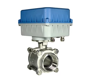
SS electric ball valve
Globe valves remain the benchmark for precision control, especially in high pressure drop situations or where specific flow characteristics are critical. Their linear motion requires a linear electric actuator.
Electric diaphragm valves excel in sanitary applications (food, pharma) or when handling corrosive fluids or slurries, as the fluid is isolated from the operating mechanism by the flexible diaphragm. However, they typically have lower pressure and temperature limits.
The choice depends on prioritizing factors like control accuracy, flow capacity, pressure handling, fluid type, and cost for the specific application.
Proper installation and commissioning are vital for ensuring your electric regulating valve performs accurately and reliably within the control system. Rushing this stage can lead to poor performance or premature failure.
Installation:
Handling: Handle the valve and actuator assembly with care. Avoid lifting by the actuator housing or manual override wheel.
Orientation: Install the valve in the preferred orientation as recommended by the manufacturer. Often, installing with the actuator upright or horizontal is preferred over having it hang below the pipe where condensation might collect. Ensure sufficient clearance for maintenance and manual operation.
Pipe Cleanliness: Ensure the pipeline is thoroughly flushed and free of debris (weld slag, dirt, scale) before installing the valve. Debris can damage seats or prevent proper closure/control. Installing a strainer upstream is often recommended.
Alignment: Ensure pipes are properly aligned and supported. Avoid using the valve to pull pipes into alignment, as this induces stress.
Connections: Use appropriate gaskets and bolt tightening procedures for flanged valves. Use suitable thread sealant for threaded connections. Do not overtighten.
Wiring: Follow all local electrical codes. Use appropriate cable glands and conduit to protect wiring. Ensure correct power supply voltage and polarity. Separate control signal wires from high-voltage power wires to minimize interference. Ensure proper grounding.
Commissioning:
Initial Checks: Verify correct wiring and power supply. Check manual override operation (if applicable).
Calibration (Stroke Check): Command the valve to fully open and fully close using the control signal (e.g., send 4mA and 20mA). Verify that the actuator drives the valve smoothly to the correct end positions and that any feedback signal accurately reflects these positions (e.g., 4mA out when closed, 20mA out when open). Many modern actuators have auto-calibration routines.
Intermediate Point Check: Send intermediate control signals (e.g., 8mA, 12mA, 16mA) and verify that the valve moves to the corresponding positions (25%, 50%, 75% open) and that the position feedback is accurate.
Control Loop Tuning: Once the valve is stroking correctly, it needs to be tuned as part of the overall control loop (e.g., PID loop in the controller). This involves adjusting the controller’s tuning parameters (Proportional, Integral, Derivative gains) to achieve stable and responsive control of the process variable (temperature, pressure, flow) without excessive oscillation or slow response. This step is critical for optimal performance.
Documentation: Record all settings, calibration data, and tuning parameters for future reference.
Following these steps helps ensure the electric regulating valve integrates correctly and performs as expected from day one.
Selecting the right partner for your electric regulating valve requirements is crucial for project success and long-term operational reliability. As a specialized smart valve manufacturing plant, we offer compelling reasons to choose us:
Deep Manufacturing Expertise: We design, engineer, and manufacture our electric regulating valves and actuators in-house. This provides us with intimate knowledge of the product, enabling superior quality control from component selection to final testing. We understand the nuances of valve design and actuator integration required for precise modulation.
Tailored Solutions: We offer a wide range of standard electric regulating valves, including various types (Proportional regulating valve, Floating point regulating valve), materials, sizes, and control options. Crucially, our manufacturing capabilities allow for customization to meet specific application requirements – whether it’s a unique flow characteristic, special materials, or integration with specific communication protocols.
Focus on Smart Technology: Our expertise extends to smart regulating type valves with advanced features like digital communication (e.g., RS485, BACnet), onboard diagnostics, and remote configuration capabilities, aligning with modern automation trends.
Assured Quality and Reliability: Quality is embedded in our production process. We utilize robust designs, high-quality materials, and rigorous testing procedures (including pressure testing and stroke calibration) to ensure every electric regulating valve meets demanding performance standards and offers reliable, long-term service.
Dedicated Technical Support: Our team includes engineers with deep expertise in fluid control and automation. We provide comprehensive pre-sales support to help you select the optimal specification and post-sales assistance for installation, commissioning, and troubleshooting. We understand the needs of Building Automation Engineers, Industrial Plant Managers, and Mechanical Contractors.
Commitment to Partnership: We aim to build long-term relationships with our clients, including System Integrators and Government Project Bidders. We offer competitive solutions, timely delivery, and the flexibility needed to support your projects effectively.
Partnering with us means gaining access to high-quality, energy-efficient, and often customizable electric regulating valve solutions, backed by the knowledge and support of a dedicated manufacturer invested in your success. We provide the complete unit, ready for integration.
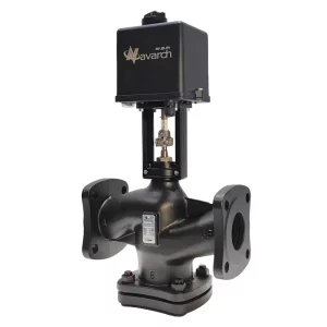
Proportional regulating valve
What does “rangeability” mean for an electric regulating valve?
Rangeability refers to the ratio of the maximum controllable flow to the minimum controllable flow that a valve can handle effectively. A higher rangeability (e.g., 50:1 or 100:1) means the valve can provide precise control over a wider range of flow rates, which is important in applications with varying loads.
Can an electric regulating valve provide tight shut-off?
It depends on the valve type and design. Electric regulating ball valves and diaphragm valves generally offer excellent (ANSI Class VI or bubble-tight) shut-off. Globe valves can also provide tight shut-off (Class IV, V, or VI) depending on the seat material (metal vs. soft) and actuator force. Always check the valve‘s shut-off class specification.
What is “fail-safe” operation in an electric regulating valve?
Fail-safe refers to the valve‘s action upon loss of power or control signal. Standard actuators are often “fail-in-place” (stay put). Fail-safe actuators use internal springs or battery backup systems to automatically drive the valve to a predefined safe position (e.g., fully open or fully closed) when power is lost, which is critical in many safety or process-critical applications.
How do I size an electric regulating valve correctly?
Sizing involves calculating the required flow coefficient (Cv or Kv) based on the desired flow rate, fluid properties (specific gravity), and the pressure drop across the valve. Manufacturers provide sizing formulas and software. It’s crucial to use the actual operating conditions. Undersizing prevents achieving maximum flow, while oversizing leads to poor control, especially at low flow rates.
What kind of maintenance do electric regulating valves typically require?
Generally, they require minimal maintenance. Periodic visual inspection for leaks, damage, or corrosion is recommended. Checking wiring connections for tightness and ensuring the actuator enclosure remains sealed is important. Depending on the service and manufacturer recommendations, occasional cycling (if the valve stays static for long periods) might be beneficial. Some actuators may log diagnostic data (feedback) that can indicate potential issues.
Are electric regulating valves suitable for hazardous environments?
Yes, electric actuators available with explosion-proof or intrinsically safe ratings (e.g., ATEX, IECEx, Class/Division) can be used in hazardous locations where flammable gases, vapors, or dust may be present. These specially designed actuators prevent ignition of the surrounding atmosphere. Ensure the entire valve/actuator assembly carries the appropriate certification for the specific hazardous area classification.
Electric regulating valves provide precise, modulating control of flow, pressure, or temperature using an electric actuator driven by a variable control signal (e.g., 4-20mA, 0-10V).
They differ from on/off valves by offering intermediate positioning between fully open or fully closed.
Key components include the valve body (globe, ball, butterfly), internal trim, and the modulating electric actuator with motor, gearing, control circuits, and position feedback.
Advantages include precision, energy efficiency, ease of automation, simplified infrastructure (vs. pneumatic), and reliable operation.
Proper selection requires careful consideration of the process fluid, flow rate, pressure, temperature, required control accuracy (rangeability), and actuator specifications (signal, speed, fail-safe, enclosure).
Common applications are found in HVAC, industrial processing (chemical, food, water treatment), power generation, and more.
Partnering with a knowledgeable manufacturer provides access to quality products, customization, smart regulating type options, and essential technical support.