WhatsApp:
+86 13188899036
Email:
[email protected]
Avoid your inquiry is delay response, please enter your WhatsApp/WeChat/Skype along with the message, so we can contact you at the very first time
We will reply you within 24 hours. If for urgent case, please add WhatsApp: +86 13188899036, or WeChat: 0531-87968777. Or call 0531-87968777 directly.
* We respect your confidentiality and all information are protected. We will only use your information to respond to your inquiry and will never send unsolicited emails or promotional messages.
Struggling with uneven heating or cooling in your building? Agitate: Fluctuating system pressures causing inefficient operation and high energy bills? Solution: Achieving stable, efficient hydronic system performance requires precise flow control, often best managed by an automatic balance valve.
An automatic balance valve operates by utilizing an internal mechanism, typically a spring-loaded cartridge or diaphragm, that dynamically adjusts the valve opening in response to changes in differential pressure across the valve. This core working principle ensures a constant flow rate is maintained through the circuit, regardless of pressure fluctuations elsewhere in the hydronic system. Its primary function is to automatically regulate the flow of water, achieving automatic balance without manual adjustment, making the circuit effectively pressure independent within its design range.
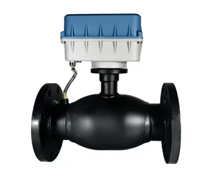
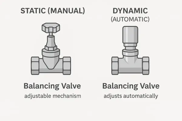
Balancing Valve Mechanism
As a leading smart valve Manufacturing plant, we understand the critical role precise flow control plays in modern building and industrial systems. We specialize in creating high-quality, energy-efficient balance valve solutions designed for seamless integration and long-term reliability. Let’s dive deep into how these essential components function.
A balance valve is a specialized type of valve used in hydronic heating and cooling systems to ensure that water flow is distributed correctly throughout the network. Think of it like traffic control for water. Without proper balancing, some circuits might receive too much flow (overflow), while others receive too little (underflow). This leads to:
Uncomfortable temperature variations between zones.
Inefficient energy use (higher pumping costs, suboptimal heat transfer).
Potential noise issues like banging pipes or whistling valves.
Difficulty in achieving desired setpoints.
In any hydronic system, whether it’s heating radiators in a multi-story office building or cooling coils in a complex industrial process, achieving the designed flow rate in each circuit is paramount. Balancing valves help achieve this precise distribution. They allow engineers and technicians to regulate the flow to each terminal unit (like a radiator, fan coil unit, or heat exchanger) according to its specific requirement. This ensures that the system operates as intended, delivering comfort and efficiency. Balancing valves play a crucial role in optimizing performance.
The importance of a balance valve cannot be overstated. Industry studies suggest that improperly balanced systems can suffer energy penalties of 10-30% or more. They prevent the “path of least resistance” problem, where water naturally favors shorter pipe runs or circuits with lower pressure drop, starving more distant or higher-resistance circuits. By introducing a controlled restriction, balancing valves ensure a more equitable distribution, making the entire hydronic system function correctly. Proper balancing valves help maintain consistent performance across all zones.
The magic of an automatic balance valve lies in its ability to self-adjust. Unlike manual balance valves that require setting and are fixed, an automatic balance valve dynamically responds to changes in the system pressure. Its core working principle revolves around maintaining a constant flow rate through its circuit, regardless of fluctuations in the differential pressure across it.
Inside the valve body of an automatic balance valve, there’s typically a cartridge containing a spring and a piston or diaphragm assembly. As the pressure differential across the valve increases (meaning more pressure pushing the water through), this internal mechanism moves to restrict the flow path, increasing the pressure drop within the balance valve itself. Conversely, if the differential pressure across the valve decreases, the mechanism opens up the flow path, reducing the internal pressure drop.
This constant adjustment ensures that the net result – the flow rate passing through the balance valve – remains stable at the pre-set or factory-calibrated value. It essentially absorbs the pressure fluctuations occurring elsewhere in the hydronic system, making the circuit pressure independent within the valve’s operating pressure range. This automatic flow regulation simplifies commissioning and ensures ongoing flow balance. As one experienced HVAC engineer noted, “Automatic balancing valves took the guesswork out of achieving stable flow in our variable volume systems.”
The primary difference lies in how they achieve flow balance and respond to system changes. Manual balance valves, often referred to as static balancing valves or double regulating valves, require a technician to manually adjust the valve opening to achieve the desired flow rate. This setting is typically fixed during the initial commissioning phase using flow measurement tools.
Here’s a table summarizing the key differences:
| Feature | Manual Balance Valve (Static) | Automatic Balance Valve (Dynamic) |
| Operation | Fixed setting, requires manual adjustment | Self-adjusting, maintains constant flow |
| Response to ΔP | Flow changes with pressure fluctuations | Flow remains constant within operating range |
| Balancing Method | Manual balancing (iterative, time-consuming) | Automatic balance (set/select & install) |
| Commissioning | Can be complex and lengthy | Faster and simpler |
| System Type | Best for constant flow systems | Ideal for variable flow systems |
| Cost | Lower initial cost | Higher initial cost, lower lifecycle cost potential |
| Performance | Good in stable systems, less so in dynamic ones | Consistently high performance in dynamic systems |
| Key Function | Creates fixed resistance | Creates variable resistance for constant flow |
While manual valves are often simpler and less expensive initially, automatic balancing valves provide superior performance and long-term efficiency, especially in variable-flow systems common in modern buildings. The choice between manual and automatic depends heavily on the specific hydronic system design and operational requirements.
The key is the internal mechanism that creates a variable resistance, acting like an internal pressure control system dedicated to flow stability. Let’s break down the working principle further:
Pressure Increase Scenario: Imagine the differential pressure across the automatic balance valve starts to increase (e.g., another zone’s control valve closes). This higher pressure pushes harder against the internal piston or diaphragm.
Mechanism Response: This force works against a calibrated spring. As the pressure overcomes the spring force, the piston/diaphragm moves, partially closing off the water passage within the valve body.
Result: This restriction increases the internal pressure drop generated by the balance valve itself. The crucial point is that the increase in the balance valve’s internal pressure drop precisely counteracts the increase in the incoming differential pressure. The net effect is that the flow rate remains constant.
Conversely:
Pressure Decrease Scenario: If the differential pressure across the balance valve drops (e.g., another zone’s control valve opens fully).
Mechanism Response: The spring force now overcomes the reduced pressure force acting on the piston/diaphragm. The mechanism moves to open the flow path wider.
Result: This decreases the balance valve’s internal pressure drop, counteracting the decrease in incoming differential pressure. Again, the flow rate will remain remarkably stable.
This dynamic pressure balancing act ensures constant flow performance. It’s a purely mechanical feedback loop happening continuously within the valve.
While designs vary slightly between manufacturers, the core components enabling the automatic balance function are generally consistent:
Valve Body: The main casing housing internal parts and connecting to pipework. Materials include brass, bronze, stainless steel, or ductile iron.
Flow Control Cartridge: The “brain” of the balance valve. This assembly usually includes:
Diaphragm or Piston: Senses the differential pressure.
Calibrated Spring: Provides the counter-force determining the flow rate and pressure range.
Orifice/Seat: The adjustable opening controlling fluid flow.
(Sometimes) Adjustment Mechanism: Allows field setting or selection of the target flow rate.
Seals and O-rings: Critical for preventing leaks, especially around the moving valve stem or cartridge.
Optional Test Ports: Allow for pressure/temperature checks, aiding diagnostics (though less critical for initial balancing than with manual valves).
As manufacturers, we focus heavily on the precision and material quality of the cartridge components, as they dictate the balance valve’s accuracy and lifespan. Our Lorawan Smart Valve incorporates these reliable mechanical principles with added smart communication capabilities.
Understanding the types of balancing valves helps clarify the role of automatic balance valves. The two main categories are:
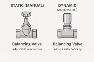
different types of balancing valves
1. Static Balancing Valves (Manual):
Characteristics: Require manual adjustment to set a fixed resistance (pressure drop) for a target flow rate. Do not adapt to system pressure changes.
Examples: Fixed orifice valves, variable orifice valves, double regulating valves.
Primary Use: Constant-flow systems, simpler hydronic circuits.
Function: Manual balancing.
2. Dynamic Balancing Valves (Automatic):
Characteristics: Automatically adjust to maintain a specific condition (constant flow or constant differential pressure).
Sub-Types:
Automatic Balance Valves (Constant Flow Regulators): Maintain a constant flow rate despite differential pressure changes. This is the focus of our article.
Differential Pressure Control Valves (DPCVs): Maintain a constant differential pressure across a circuit or sub-branch, ensuring stable pressure for other devices like control valves.
Primary Use: Variable-flow systems, complex circuits, ensuring stability for control valves.
Function: Provide automatic balance, pressure independent flow control (ABVs), or pressure control (DPCVs).
Therefore, an automatic balance valve is a specific type of dynamic balancing valve designed for constant flow regulation.
The operating pressure range is a crucial specification. This defines the minimum and maximum differential pressure across the valve (ΔP) within which it can accurately maintain a constant flow rate.
Below Minimum ΔP: Insufficient pressure to activate the mechanism correctly; flow rate may be lower than target.
Above Maximum ΔP: Mechanism may be unable to restrict flow enough, potentially causing noise (cavitation), wear, or loss of control. Flow rate might exceed the target.
Typical Operating Ranges (ΔP):
Low Pressure: ~2-35 PSI (14-240 kPa)
Standard Pressure: ~5-50 PSI (35-345 kPa)
High Pressure: ~10-80+ PSI (69-550+ kPa)
Fact: Selecting a valve with the appropriate ΔP range is vital. A mismatch can negate the benefits of automatic balancing. System designers must calculate the expected ΔP variations in the specific circuit. As manufacturers, we, like others such as Red-White Valve Corp, provide clear specifications for each balance valve model.
Balancing valves, both manual and automatic, are fundamental in numerous hydronic systems. Their goal is always to balance the flow rates. Here are key applications of balancing:
HVAC Systems:
Heating: Radiators, baseboards, radiant floors (ensuring even heat).
Example: In a large hotel, automatic balance valves on each room’s fan coil unit ensure consistent heating/cooling regardless of how many other rooms are calling for conditioning.
Cooling: Fan coil units (FCUs), air handling units (AHUs), chilled beams (maintaining correct chilled water flow).
Variable Air Volume (VAV) Reheat: Ensuring proper water flow to VAV box coils.
Primary/Secondary Loops: Managing flow and pressure between circuits.
Geothermal/Heat Pumps: Optimizing flow rate through loops for efficiency.
Industrial Processes:
Process Temperature Control: Maintaining precise fluid flow rates for cooling molds, controlling reactor temperatures, etc.
Example: A plastics manufacturer uses automatic balance valves on cooling lines for injection molds to ensure consistent part quality by maintaining stable cooling flow rates.
Heat Exchangers: Achieving design flow rates for maximum efficiency.
Utility Distribution: Balancing flow in large campus or plant-wide heating/cooling networks.
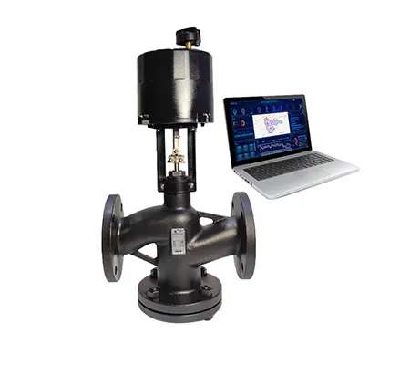
In these diverse applications of balancing, automatic balance valves shine where loads vary, simplifying control and boosting efficiency. We offer solutions tailored for these needs, including robust options like our Electric regulating valve for modulating control alongside balancing elements.
Proper hydronic balancing is not just about comfort; it’s fundamentally linked to energy efficiency. An unbalanced hydronic system is an inefficient one.
Reasons Why Balancing is Crucial:
Prevents Overflow & Poor Delta T: Unbalanced systems often have low ΔT (temperature difference between supply and return water) due to overflow in low-resistance circuits. This forces boilers/chillers to run more often and pumps to work harder. Data Point: Improving system ΔT by even a few degrees can yield significant energy savings. Automatic balance valves inherently prevent overflow.
Eliminates Underflow & Discomfort: Starved circuits lead to comfort complaints and attempts to override controls, further destabilizing the system. Balancing valves ensure design flow reaches all zones.
Reduces Pump Energy: Balanced systems allow pumps to operate closer to their design efficiency point, often at lower speeds. Fact: According to Pump Affinity Laws, a 20% reduction in pump speed can reduce energy consumption by nearly 50%.
Improves Control Valve Authority: Stable differential pressure across control valves (often aided by DPCVs or inherent in PICV designs) allows them to modulate accurately, preventing temperature hunting and waste.
Enhances System Longevity: Reduces strain and potential cavitation issues in pumps and valves, leading to longer equipment life.
“Achieving good hydronic balance is often the single most effective step toward optimizing HVAC energy performance after initial design,” notes a common sentiment among energy auditors. Our RS485 regulating valve provides precise control, which works best in a well-balanced system.
Choosing the correct automatic balance valve requires careful consideration. As manufacturers advising diverse clients (Engineers, Integrators, Plant Managers, Contractors), we highlight these key factors:
Target Flow Rate (GPM or l/s): Must match the circuit’s design requirement. Select pre-set or adjustable models accordingly.
Operating ΔP Range: Ensure the valve’s range covers the circuit’s expected minimum and maximum differential pressure.
Pipe Size & Connection: Match existing pipework (e.g., 1/2″, DN20) and connection type (NPT, BSP, sweat, flange).
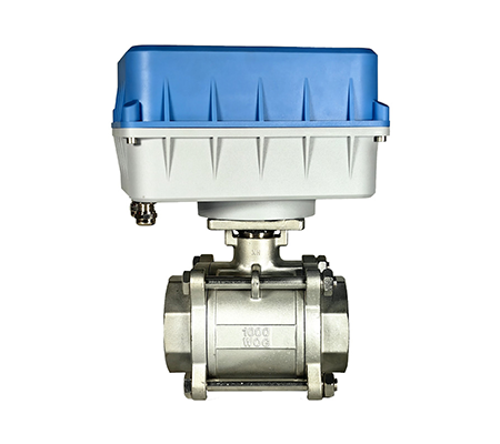
Fluid Compatibility & Temperature: Verify materials (valve body, seals) suit the fluid (water, glycol mix) and temperature range. Consider stainless steel options like an SS electric ball valve body for corrosive fluids, though its primary function differs.
Accuracy Tolerance: Choose based on application needs (e.g., +/- 5% or +/- 10% of target flow rate).
Max Static Pressure & Temp: Ensure ratings exceed system test pressures and maximum operating temperatures.
Required Features: Integrated shut-off, test ports, adjustable settings needed?
Manufacturer Credibility: Look for quality, support, warranty, and clear technical documentation. We stand behind our products like the reliable intelligent valve.
Checklist: Use these points as a checklist when specifying or purchasing an automatic balance valve.
How do you set an automatic balancing valve?
Many automatic balance valves come factory pre-set for a specific flow rate. Others have an adjustment dial, interchangeable orifice sizes, or cartridges allowing you to select the target flow rate. Unlike manual balance valves, there’s no complex flow measurement and iterative adjustment needed across the system during commissioning; you set the desired flow rate on the valve itself before or during installation.
What is the difference between a balancing valve and a control valve?
A balance valve (static or dynamic) primarily aims to achieve correct flow distribution and stability (flow balance). An automatic balance valve specifically maintains a constant flow. A control valve modulates the amount of flow (from 0% to 100%) based on a signal (e.g., from a thermostat) to control temperature. While both regulate the flow of water, balancing valves focus on distribution, automatic balance valves on constant flow, and control valves on modulation for temperature. Pressure Independent Control Valves (PICVs) integrate both functions.
Can an automatic balance valve shut off flow completely?
Typically, no. Standard automatic balance valves are designed to regulate flow down to their minimum controllable level, not provide bubble-tight shut-off. For maintenance isolation, a separate shut-off valve (ball, gate) should be installed in series. Some specialized combination valves might include this feature.
Are automatic balancing valves more expensive than manual balancing valves?
Yes, the initial unit cost is generally higher. However, Fact: Commissioning labor savings for automatic balance valves can be substantial, often cited as 50-70% faster than traditional manual balancing procedures for complex systems. When combined with long-term energy savings and stable performance, the total cost of ownership often favors automatic valves in variable flow systems.
Where should automatic balancing valves be installed in a hydronic system?
The most common recommendation is installation on the return side of the terminal unit (radiator, coil) or circuit. This placement helps provide a stable pressure environment for the control valve, which is typically on the supply side. Always follow the specific manufacturer’s installation guidelines, including requirements for straight pipe lengths.
How long do automatic balancing valves typically last?
A high-quality automatic balance valve, like those we manufacture, installed correctly in a well-maintained system (clean fluid, within pressure/temp limits) can be expected to last 15-25 years or more. Material quality (e.g., dezincification-resistant brass, robust stainless steel springs) and design precision are key longevity factors.
Key Takeaways on Automatic Balancing Valve Working Principle:
Core Function: Maintain constant flow rate despite differential pressure changes.
Mechanism: Internal spring/diaphragm or piston dynamically adjusts valve opening.
Benefit: Achieves automatic balance, simplifies commissioning, improves efficiency, ensures comfort.
Key Spec: Operating pressure range (ΔP) is critical for proper selection.
Comparison: Offers significant advantages over manual balance valves in variable flow systems.
Placement: Typically installed on the return side of circuits.
Value: Higher initial cost often offset by commissioning savings and long-term energy efficiency.
As a dedicated manufacturer of smart valve solutions, we are committed to providing high-performance balancing valves and other flow control technologies. From reliable automatic balance valves to advanced network-enabled solutions like our WiFi Smart Valve or 4G Smart Valve, we offer the expertise and product range to meet the demanding needs of modern building and industrial systems. Contact us today to explore how our valve solutions can optimize your hydronic system performance and efficiency.