WhatsApp:
+86 13188899036
Email:
[email protected]
Avoid your inquiry is delay response, please enter your WhatsApp/WeChat/Skype along with the message, so we can contact you at the very first time
We will reply you within 24 hours. If for urgent case, please add WhatsApp: +86 13188899036, or WeChat: 0531-87968777. Or call 0531-87968777 directly.
* We respect your confidentiality and all information are protected. We will only use your information to respond to your inquiry and will never send unsolicited emails or promotional messages.
I once worried about uneven heating and cooling in my building, causing frequent complaints from every corner.
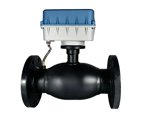
A balance valve helps regulate fluid flow in HVAC or water systems, ensuring consistent heating, cooling, or water distribution across all zones. It prevents energy waste, lowers costs, and promotes stable system performance.
I discovered how essential balancing valves are after I experienced hot spots and cold spots in various rooms. Properly installed and adjusted, they solve flow imbalances while keeping energy consumption under control.
Have you ever dealt with uncontrolled temperatures, frustrated tenants, or unpredictable water pressures in your building?
Balancing valves are typically used in HVAC systems1, hydronic heating, chilled water loops, and domestic hot water lines. They keep fluid distribution even and prevent over- or under-supply in different zones.
Balancing valves appear in many places. I’ve installed them in high-rise buildings to distribute hot water evenly to every apartment. I’ve also used them in large office complexes, ensuring that farthest zones get enough chilled water in the summer. Without balancing, the first taps or coils might hog most of the flow, leaving distal points under-supplied. That causes issues like uneven temperatures, occupant complaints, and wasted energy.
In central heating systems, hot water travels from the boiler to radiators or fan coils. Without balancing valves, the radiators closest to the boiler might receive most of the hot water, leaving distant zones cold. A balancing valve on each radiator or branch line lets me control and match flow to the heating load. This stops the system from overworking, ensuring consistent comfort.
For chilled water loops, the principle is the same. Chillers produce cold water that flows through air handlers or fan coils. Well-chosen balancing valves ensure that each coil gets the right flow, improving humidity control and temperature stability. By fine-tuning valve positions, I avoid coil freeze-ups and ensure uniform cooling.
Balancing valves also help keep hot water lines equally pressurized. In tall or sprawling buildings, balancing valves prevent hot water from lingering in supply lines unused, which can cause temperature drops or waste energy in recirculation systems. Balancing ensures each branch remains at the correct temperature, reducing wait times for hot water at distant taps.
Manufacturing plants and labs often rely on accurate flows for chemical mixing or specialized cooling tasks. I’ve seen them install balancing valves to dial in precise flow rates. This helps maintain product quality, ensures stable reaction conditions, and lowers the risk of equipment damage from inconsistent coolant flow.
Here’s a simple table summarizing common balancing valve applications:
| Application | Purpose | Outcome |
|---|---|---|
| HVAC Heating Systems | Ensure even heat distribution | Uniform room temperatures |
| Chilled Water Loops | Prevent coil starvations | Consistent cooling, humidity control |
| Domestic Hot Water Lines | Maintain recirculation, reduce wait times | Energy savings, immediate hot water |
| Industrial Processes | Precise flow regulation for chemical or coolant lines | Stable, high-quality production |
Overall, balancing valves appear wherever fluid flow must be shared fairly among multiple branches. By focusing on these valves in my projects, I notice increased occupant comfort, fewer complaints, and lower energy bills. They’re a hidden hero in fluid distribution systems, solving problems before they escalate into major inefficiencies.
Have you ever been confused about how a small valve can fix such large temperature or flow inconsistencies?
A balance valve uses an adjustable mechanism (like a calibrated orifice) to limit flow. By setting each valve to a target flow, the entire system stays balanced, delivering consistent performance.
I remember feeling overwhelmed the first time I saw “balancing valve2” in a design specification. But once I understood its principle, it made sense. A balancing valve is essentially a specialized control valve with a built-in ability to measure and restrict flow precisely. Let’s break it down:
Balancing valves often feature an adjustable stem or cartridge that restricts the flow path. Think of it like a partially closed gate, fine-tuned to let only a set volume of water pass through. When you’re setting up the system, you measure the actual flow (maybe using a handheld meter or built-in measuring ports) and adjust the balancing valve until it hits the design flow. Once set, the valve remains in that position.
Inside the valve, you might find:
Balancing a system means ensuring each branch has the design flow rate. Let’s say you have 10 fan coil units, each requiring 5 GPM. Without balancing, the coil closest to the pump might take 8 GPM, starving those farther away. By partially closing the balancing valve at the first coil, you introduce a deliberate pressure drop. That forces leftover flow onward to the other coils. Carefully repeating this step for each coil yields an even distribution.
Here’s a simplified conceptual flow of how this works:
| Step | Action |
|---|---|
| Initial Condition | All valves open, flows not measured yet |
| Measure Flow | Hook up a flow meter or read built-in gauge |
| Adjust Valve Position | Rotate stem to reduce or allow more flow |
| Check Pressure Drop | Ensure each circuit matches design specs |
| Lock Valve Setting | Secure position to prevent accidental shifts |
Some valves are “static” balancing valves, fixed at a certain position. Others are “dynamic” or pressure-independent control valves, automatically adjusting to pressure changes in the system. Static balancing valves are simpler and cheaper, but dynamic versions maintain flow without repeated manual readjustment if loads shift.
When I first installed dynamic balancing valves, I was amazed by how they self-regulate flow under varying pump pressures. That reduces commissioning time and accommodates changes like partial building occupancy or variable speed pumps.
Having a balanced system also simplifies diagnostics. If each coil or branch is guaranteed the right flow, you can quickly identify other causes (like a failing pump or air in the line) if comfort issues arise. Over time, you’ll appreciate how balancing supports stable, predictable system operation.
I once wondered if it mattered which side of the coil or radiator got the balancing valve.
Balancing valves can be placed on either the supply (flow) or the return side3. The choice often depends on the system design, but many professionals prefer the return side for easier measurement and reduced turbulence.
Choosing whether to put the balancing valve on the flow or return line often sparks debate. In my early jobs, I followed engineer’s drawings that placed them on the return side. Later, I encountered systems placing them on the supply. Either approach can work, but there are reasons why you might choose one over the other.
A short table of pros and cons:
| Placement | Pros | Cons |
|---|---|---|
| Return Side | Lower fluid temp, stable measurement | Slightly higher return piping cost |
| Supply Side | Immediate flow control at entry | Potentially hotter fluid, more turbulence |
As a rule of thumb, I prefer the return side. It’s a tradition among many engineers, especially in hydronic heating. But if the manufacturer’s instructions or the mechanical design calls for a supply-side valve, that can also be valid. The key is consistency across the entire system, ensuring you don’t mix up placement and cause confusion during commissioning.
Lastly, modern “automatic flow control” or “pressure-independent” valves often go on the coil’s return by default, simplifying measurement. In my experience, consistent installation across all loops helps keep maintenance straightforward, so I rarely deviate unless a specific design reason arises.
At first, I thought circuit setters were just a fancy name for balancing valves. Then I learned there are some differences in how they’re used.
A balancing valve is a broad term for valves that adjust and measure flow. A circuit setter is a specific brand or style of balancing valve with built-in measurement ports for easier flow reading.
If you browse mechanical catalogs, you’ll see “Circuit Setter4,” “Balance Valve,” “Flow Control Valve,” or “Manual Balancing Valve.” They generally do the same job: limiting or throttling flow to achieve system balance.
“Circuit Setter” is a term famously used by Bell & Gossett. It’s effectively a manual balancing valve that includes:
Engineers often specify “Circuit Setters” by brand name, but other manufacturers produce similar valves under different product lines. The core function remains limiting and measuring branch flows in hydronic or chilled water systems.
| Feature | Basic Balancing Valve | Circuit Setter (Trademark) |
|---|---|---|
| Measurement Ports | Possibly none or optional add-ons | Built-in P/T ports for easy measurement |
| Calibration | May have approximate markings | Detailed scale with memory stops |
| Usage Complexity | Requires external flow measurement | Faster, more straightforward commissioning |
| Typical Brand Examples | Many generic or brand-specific | Bell & Gossett “Circuit Setter” |
In my experience, a Circuit Setter is often simpler for balancing jobs. You connect your meter, read differential pressures, and find flow from a manufacturer’s chart. Then you turn the handle to get the flow you want. It’s methodical. Standard balancing valves can achieve similar results, but you may need an external gauge device that clamps onto the pipe or special test fittings. That’s more steps and equipment.
Circuit Setters also usually come with a “memory stop.” So if I close the valve for maintenance, I can reopen it to the same setting. This ensures I don’t lose the carefully tuned flow. Some basic balancing valves also provide this feature, but not always. The brand’s approach to user-friendly balancing might differ.
Ultimately, the differences can be subtle. If you see “Circuit Setter” in a specification, it usually means a manual balancing valve with integrated measurement features. If you see “balancing valve,” it might be a generic version or a different brand. Either way, they serve the same essential function: restricting flow to meet design conditions. The main difference is how easy it is to measure and document the final settings.
Balancing valves ensure every part of your system gets the right flow, preventing hot or cold spots, saving energy, and keeping users comfortable.
Learn about HVAC systems to see how balancing valves fit into the larger picture of heating and cooling efficiency. ↩
Explore this link to gain a deeper understanding of balancing valves and their crucial role in HVAC systems. ↩
Exploring the benefits of return-side installation can help you make informed decisions for your heating system. ↩
Explore this link to understand the specific features and benefits of Circuit Setters in HVAC applications, enhancing your knowledge on flow control. ↩