WhatsApp:
+8613188899036
Email:
[email protected]
Avoid your inquiry is delay response, please enter your WhatsApp/WeChat/Skype along with the message, so we can contact you at the very first time
We will reply you within 24 hours. If for urgent case, please add WhatsApp: +8613188899036, or WeChat: 0531-87968777. Or call 0531-87968777 directly.
* We respect your confidentiality and all information are protected. We will only use your information to respond to your inquiry and will never send unsolicited emails or promotional messages.
I used to rely on manual valves, constantly turning handles during emergencies.
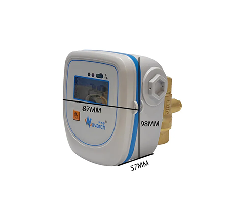
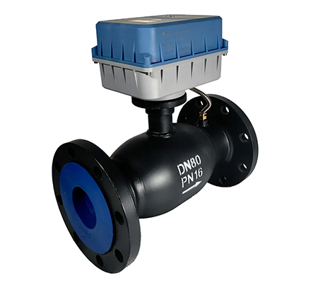
The function of a valve actuator is to move a valve open or closed automatically using electric, pneumatic, or hydraulic power, ensuring consistent and remote flow control.
Once I began using actuators, I realized they transform any mechanical valve into a smart, responsive component that fits modern automation systems. Let’s explore how they work and why they matter.
I’ve heard engineers confuse valves with actuators during meetings—leading to wrong parts being ordered.
A valve is a mechanical device1 that regulates fluid flow. A valve actuator is the power-driven mechanism that operates the valve automatically or remotely.
Let me break it down with a simple comparison. The valve is like a gate—it can stop, start, or regulate the movement of a fluid. But it needs someone—or something—to operate it. That’s where the actuator comes in.
A valve actuator is the "motor" that powers the valve. It can open or close the valve, or move it to a specific position. Instead of manual labor, it uses electricity, compressed air, or hydraulic pressure.
Here’s a side-by-side overview:
| Component | Function | Requires External Force? | Automatable? |
|---|---|---|---|
| Valve | Stops or allows fluid to pass | Yes (manual or powered) | No |
| Valve Actuator | Provides the motion to move the valve | Yes (but automated) | Yes |
In my own projects, I use the actuator to automate building systems. It allows precise, real-time control based on temperature, pressure, or flow demands. Without the actuator, the valve is just a static piece of metal.
This distinction is crucial when designing systems or ordering parts. Specifying both the valve and its actuator ensures everything fits, works, and responds correctly under real-world conditions.
I used to think “electric control valve” just meant “electrically operated valve.” But I learned it’s more than that—it’s a complete system with feedback, logic, and precision.
An electric control valve works by receiving control signals from a system controller, then adjusting valve position using an electric actuator to regulate flow, pressure, or temperature in real-time.
Electric control valves combine three main parts:
When the system needs to change the flow (based on sensor input), it sends a signal to the actuator—typically 4–20mA or 0–10V DC. The actuator reads this signal and adjusts its internal motor. That motor then moves the valve stem or disc to the required position.
If, for example, the signal is “12 mA,” and the full range is 4–20mA, the actuator knows to open the valve to about 50%. The valve holds this position until the signal changes. Feedback mechanisms (like position encoders or limit switches) verify movement and send the current valve position back to the controller.
Here’s a simplified signal-response cycle:
| Step | Action |
|---|---|
| System sends control signal | 4–20 mA / 0–10 V based on real-time data |
| Actuator receives signal | Converts signal to valve position via internal motor |
| Valve adjusts flow | Flow changes to meet target temperature/pressure/volume |
| Feedback sent | Actuator confirms valve position to central controller |
In my HVAC projects, I use electric control valves to balance chilled water loops. The actuator modulates the valve to maintain room temperature based on thermostat feedback. This closed-loop operation2 delivers precise, responsive comfort and helps reduce energy use.
Without this electric control loop, the system becomes either manual or binary (on/off), leading to inefficiencies. So, an electric control valve ensures smooth, stable, and automated performance.
At first, I wondered if actuators were just for convenience—but I learned they are essential in smart systems.
The purpose of an actuator is to automate valve operation3, enabling fast, remote, and precise flow control based on system demands without manual effort.
I used to send technicians to manually adjust valves every time flow or pressure needed tweaking. That was inefficient and prone to human error.
When I introduced actuators, I unlocked new advantages:
Here’s why this matters:
| Function | Value Delivered |
|---|---|
| Real-time responsiveness | Handles rapid system changes without delays |
| Consistent accuracy | Maintains stable process conditions (e.g., temperature) |
| Integration with sensors | Enables smart automation and safety shut-offs |
| Reduced labor | Cuts manual interventions and staffing needs |
| Safer operation | Avoids human exposure to dangerous or remote areas |
In high-pressure systems or hazardous environments (like chemical or gas lines), actuators remove risk. I can shut down a valve in seconds with a remote signal. In a factory with dozens of control points, this efficiency multiplies.
Modern actuators even include diagnostics—detecting faults, reporting wear, or alerting you to unusual torque loads. That’s smart maintenance.
In short, actuators go beyond convenience. They are a foundation for intelligent, safe, and energy-efficient fluid control.
When I started using smart HVAC components, I wanted to understand how the actuator actually turned a signal into motion.
The principle of an electric control valve actuator4 is to convert an electrical signal into mechanical motion—rotational or linear—to move a valve to a desired position.
Electric control actuators follow a simple but effective principle: signal in → motor movement → valve adjustment → position feedback.
Let’s look at this in more detail.
The actuator receives a command, typically:
This signal represents the desired valve position. For example:
The actuator’s internal controller reads the input and powers a motor. Through reduction gears, this motor moves either:
The motion is smooth and controlled to prevent water hammer or wear.
A sensor, such as a potentiometer or encoder, constantly checks the valve’s position. If the actuator moves too far or too little, it corrects itself. This feedback loop ensures accuracy and system stability.
Actuators also monitor motor torque. If resistance is too high (for example, a blocked valve), the actuator can:
Summary table:
| Actuator Function Step | What Happens |
|---|---|
| Signal Input | Receives target position |
| Power Conversion | Electrical power activates motor and gears |
| Mechanical Motion | Valve stem or disc moves accordingly |
| Feedback Loop | Confirms position, corrects deviations |
| Safety Monitoring | Detects overloads, stalls, or errors |
I’ve applied this principle across many industries—from water treatment to energy plants. Once installed, electric actuators provide reliable control for years, needing minimal maintenance. They give me full visibility and fine-tuned performance in automated systems.
Understanding this principle helps me select the right model, configure settings, and integrate the actuator into larger control platforms.
A valve actuator’s function is to automate and control valve movement using signals, making fluid systems smarter, safer, and more efficient.
Mechanical devices play a crucial role in various industries. Discover more about their types and uses to enhance your knowledge. ↩
Learning about closed-loop operations will provide insights into automated systems and their advantages over manual controls. ↩
Understanding the significance of automating valve operation can enhance your knowledge of smart systems and their efficiency. ↩
Explore this link to gain a deeper understanding of electric control valve actuators and their applications in various industries. ↩